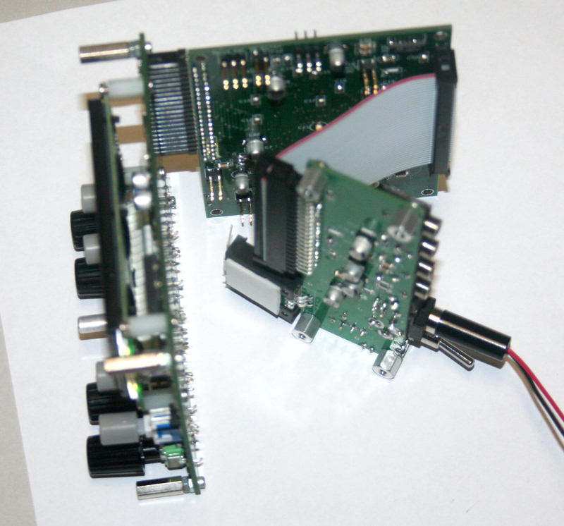
By now you should have the DSP, Controls and I/O
boards complete. Also, you need to at least have Cable #1 made from
the Internal Cable Kit. (Cable 1 enables
you to connect the DSP and I/O boards.)
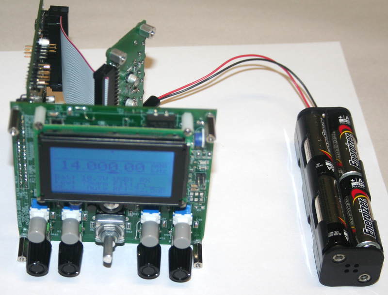
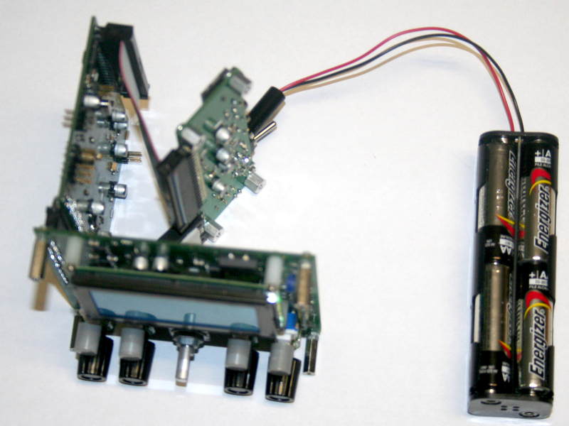
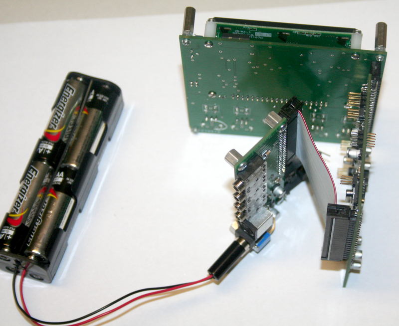
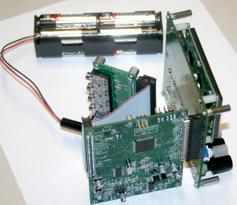
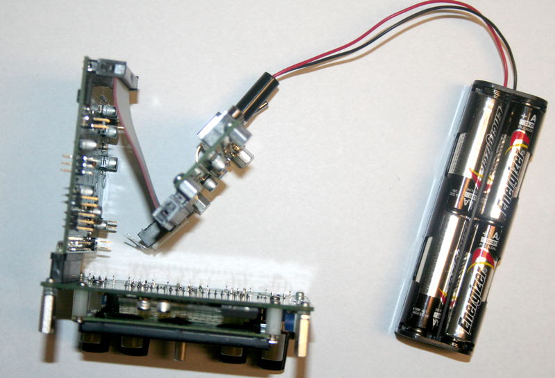
Connect the boards as shown in the photos below,
and attach a 12V power source - ideally a battery as shown, or a current
limited at 200 ma.
Apply power and turn on the power switch on the
I/O board (flip it "down" toward the I/O pc board). NOTE:
Be careful that the mounting tabs of the voltage regulator hanging off the
I/O board don't touch the bottom of the DSP board!
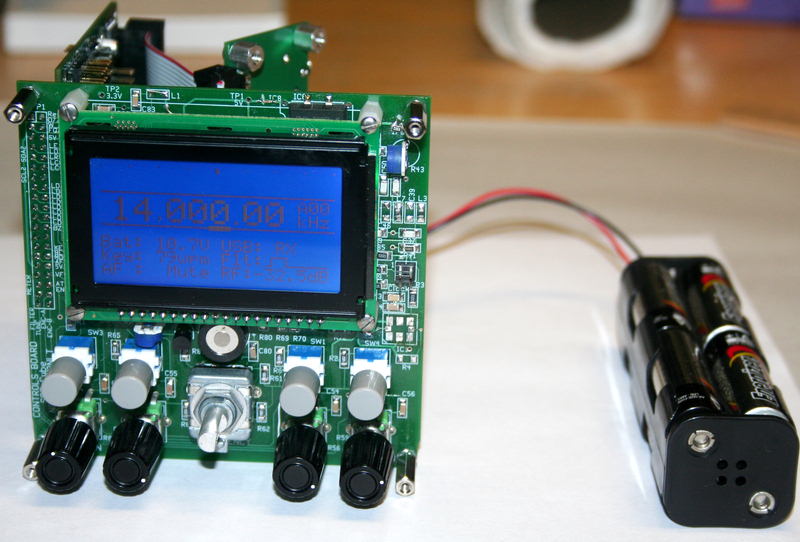
You should now see the LCD illuminated with a
blue light. Using a pointed object such as the end of an Exacto blade,
carefully move the R71 "Contrast" trimmer pot (located on the Controls board
just below the LCD) until you see the characters and graphics appear in a
bright, clear manner.
If you have a way of measuring the power supply
current being supplied to the SDR Cube board set, it should be about 130 ma.
Anything significantly more or less than this indicates problems and you
should go down to the Troubleshooting section of this page.
Rudimentary tests ...
You should be able to ...
-
turn the RF Atten pot on the Controls board
and see the RF Level numbers change in the display ...
we wrapped two separate functions
into this control: changing the state of the two cascaded attenuator
pads on the RxAmp board of the Softrock, and changing the Codec gain
settings for the receive path. Thus a wide range of attenuation may be
achieved with a single control. If you look at the displayed
attenuation level on the display while turning the control
counter-clockwise, you will see an �overlapping set of four ranges�
displayed that might be considered like a sawtooth pattern of numbers.
Those four ranges relate to the four settings available from the
two-stage attenuator pads on the RXAMP board. And when continuing to
turn the control within each of those four ranges, the Line In gain of
the codec (i.e., software level control) is smoothly changed to allow
one to achieve the perfect level setting for the RF signal level being
tamed.
-
turn the AF Gain pot on the Controls board
and see the AF Gain numbers change in the display
-
turn the Filter pot on the Controls board
and see the filter graphic correspondingly move
-
turn the Frequency dial and see the
displayed frequency change
-
press the Menu button and see the User menu
appear. (Press again to get back to the operational display.)
-
press the Rate button repeatedly and see the
underscore cursor move among the frequency digits
-
press the Mode button repeatedly and see the
Mode status indication on the display cycle from CW to USB to LSB
-
press the VFO button and see the A/B VFO
indicator on the display change
[More ...]
LED power-on sequencing definition ...
When you power-up the Cube, the red and green LEDs on the DSP will
illuminate in a way that provides useful diagnostic information about the
health of your Cube boards ...
-
Both LEDs are turned on when the software
starts after power-up.
-
LD3 (Red) is turned off after the external
EEPROM (IC1) communications is determined to be okay.
-
The splash screen next shows on the Cube
display and a start-up beep tone is delivered.
-
LD4 (Green) is turned off after the Si570 or
DDS initialization. If LD4 stays on, an Si570 I2C bus problem probably
exists.
-
LD4 (Green) is SW heart beat indication
during normal Cube operation, slowly flashing on/off at 1 second
intervals.
-
LD3 (Red) is ADC over load indicator for
both channels, and it is illuminated when the signal levels are too high
in the ADC.
Extended Tests using the Aux serial port the
Terminal Menu...
Construct the Aux Cable serial port adapter, as
shown in the diagram, and connect
the Cube to a PC running a terminal program (TeraTerm, HyperTerm,
ProComm, et al.
When you power up the Cube, you will see the
Terminal Menu displayed on the PC screen, offering a number of useful
command for testing and exercise of the Cube.
SDR Cube SW started
George Heron N2APB / Juha Niinikoski OH2NLT
Version: v1.00
Date: 07.11.2010
CPU speed, FCY = 38707200 Hz
24LC256 EEPROM I/O init
User data restored succesfully
Timer system started
ADC system started
Battery voltage = 11.6V
DSP filters initialized
Codec started
Si570 I2C init
DDS started
Si570 LO selected
Change Terminal UART to user baud rate 9600
Change PSK Modem UART to user baud rate
9600
SDR Cube UART user baud rate = 9600
Starting Main
---- SDR Cube Test Commands,Ttstamp =
8(s) ----
Battery voltage = 11.6V
i print system info
a print ADC data
p print I/O port data
e read Encoder & switch
t test tones
d test PWM DACs
o test RF attenuator relay outputs
x print Si570 factory XTAL freq
l test LCD
r Read EEPROM
---- SDR Cube Debug Commands, see source
code for details ----
q op
mode flags
s print
Si570 registers
c set Codec DCI mode
v Codec volume controls
m Mic On / Off switch
1 Show LCD characters (chgen test)
2 Write LCD
3 Write Large LCD
w Write EEPROM, Caution cauce factory
default reset at next start
[More ...]
That's it for now ... you have a minimally
operational SDR Cube! In the next installment of this Assembly Guide,
we'll go through a more deliberate and exacting set of operational checks,
including audio, paddle input, Morse output, etc. Also a detailed
Troubleshooting section to assist in finding/correcting problems.
Click on any of the photos below to see a
larger view ...